Quantcast
Channel: Processors forum - Recent Threads
Viewing all 17527 articles
Browse latest View live

DRA726: remoteproc issue

$
0
0

Part Number: DRA726

I have 4 analog camera inputs using an ISL79987 device

I have no problem displaying the 4 video inputs using waylandsink and VPE

isl79987               10732  1
ti_cal                 24471  0
videobuf2_dma_contig     8697  2 ti_cal,ti_vpe
videobuf2_memops        1824  1 videobuf2_dma_contig
videobuf2_v4l2         21752  3 v4l2_mem2mem,ti_cal,ti_vpe
videobuf2_core         25666  4 v4l2_mem2mem,ti_cal,ti_vpe,videobuf2_v4l2

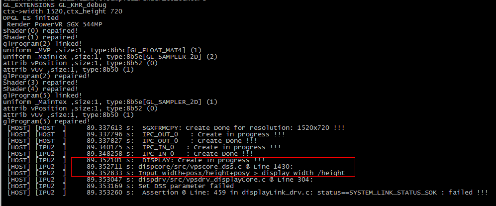
When trying to convert to MP4 there is a problem. I did notice an error message with dmesg

[    3.443601] ledtrig-cpu: registered to indicate activity on CPUs
[    3.451174] omap-rproc 55020000.ipu: assigned reserved memory node ipu2_cma@95800000
[    3.472701]  remoteproc0: 55020000.ipu is available
[    3.477600]  remoteproc0: Note: remoteproc is still under development and considered experimental.
[    3.502659]  remoteproc0: THE BINARY FORMAT IS NOT YET FINALIZED, and backward compatibility isn't yet guaranteed.
[    3.522764]  remoteproc0: Direct firmware load for dra7-ipu2-fw.xem4 failed with error -2
[    3.530975]  remoteproc0: Falling back to user helper

/lib/firmware

drwxr-xr-x 4 root root    4096 Nov 21 13:25 .
drwxr-xr-x 9 root root    4096 Nov 20 22:09 ..
lrwxrwxrwx 1 root root      40 Nov 19 22:05 dra7-ipu2-fw.xem4 -> /lib/firmware/dra7-ipu2-fw.xem4.ipumm-fw
-rw-r--r-- 1 root root 3743144 Nov 19 19:22 dra7-ipu2-fw.xem4.ipumm-fw
-rw-r--r-- 1 root root  572182 Nov 19 19:22 dra7-ipu2-fw.xem4.map
drwxr-xr-x 2 root root   12288 Nov 19 19:36 emmy-w1-sdiouart
drwxr-xr-x 2 root root    4096 Nov 19 19:36 mrvl
-rw-r--r-- 1 root root    4002 Nov 19 16:14 vpdma-1b8.bin

root@actia-dra726-12inch:/lib/firmware# dir /dev/rpmsg-dce
crw------- 1 root root 245, 1 Nov 21 13:25 /dev/rpmsg-dce

crw------- 1 root root 245, 1 Nov 21 13:25 /dev/rpmsg-dce
root@actia-dra726-12inch:/lib/firmware# dmesg | grep ipu2
[    0.000000] Reserved memory: initialized node ipu2_cma@95800000, compatible id shared-dma-pool
[    3.451137] omap-rproc 55020000.ipu: assigned reserved memory node ipu2_cma@95800000
[    3.522732]  remoteproc0: Direct firmware load for dra7-ipu2-fw.xem4 failed with error -2
[    9.828431]  remoteproc0: Booting fw image dra7-ipu2-fw.xem4, size 3743144

In this test I have a PAL DVD player connected to /dev/video0

I get similar results with a camera or my video signal generator.

I haven't tested this way with my NTSC cameras yet, I would assume similar results.

Here is the command used

gst-launch-1.0 -v v4l2src device=/dev/video0 ! video/x-raw,interlaced=true ! vpe ! ducatih264enc ! queue ! h264parse ! mp4mux ! filesink location=test.mp4        

Setting pipeline to PAUSED ...
Pipeline is live and does not need PREROLL ...
Setting pipeline to PLAYING ...
New clock: GstSystemClock
/GstPipeline:pipeline0/GstV4l2Src:v4l2src0.GstPad:src: caps = "video/x-raw\,\ format\=\(string\)UYVY\,\ framerate\=\(fraction\)100/1\,\ width\=\(int\)720\,\ height\=\(int\)576\,\ interlace-mode\=\(string\)interleaved\,\ pixel-aspect-ratio\=\(fraction\)1/1\,\ colorimetry\=\(string\)bt601\,\ interlaced\=\(boolean\)true"
/GstPipeline:pipeline0/GstCapsFilter:capsfilter0.GstPad:src: caps = "video/x-raw\,\ format\=\(string\)UYVY\,\ framerate\=\(fraction\)100/1\,\ width\=\(int\)720\,\ height\=\(int\)576\,\ interlace-mode\=\(string\)interleaved\,\ pixel-aspect-ratio\=\(fraction\)1/1\,\ colorimetry\=\(string\)bt601\,\ interlaced\=\(boolean\)true"
/GstPipeline:pipeline0/GstVpe:vpe0.GstPad:src: caps = "video/x-raw\,\ format\=\(string\)NV12\,\ width\=\(int\)720\,\ height\=\(int\)576\,\ pixel-aspect-ratio\=\(fraction\)1/1\,\ framerate\=\(fraction\)100/1"
/GstPipeline:pipeline0/GstDucatiH264Enc:ducatih264enc0.GstPad:src: caps = "video/x-h264\,\ alignment\=\(string\)au\,\ stream-format\=\(string\)byte-stream\,\ width\=\(int\)720\,\ height\=\(int\)576\,\ pixel-aspect-ratio\=\(fraction\)1/1\,\ framerate\=\(fraction\)100/1"
/GstPipeline:pipeline0/GstQueue:queue0.GstPad:src: caps = "video/x-h264\,\ alignment\=\(string\)au\,\ stream-format\=\(string\)byte-stream\,\ width\=\(int\)720\,\ height\=\(int\)576\,\ pixel-aspect-ratio\=\(fraction\)1/1\,\ framerate\=\(fraction\)100/1"
/GstPipeline:pipeline0/GstH264Parse:h264parse0.GstPad:sink: caps = "video/x-h264\,\ alignment\=\(string\)au\,\ stream-format\=\(string\)byte-stream\,\ width\=\(int\)720\,\ height\=\(int\)576\,\ pixel-aspect-ratio\=\(fraction\)1/1\,\ framerate\=\(fraction\)100/1"
/GstPipeline:pipeline0/GstQueue:queue0.GstPad:sink: caps = "video/x-h264\,\ alignment\=\(string\)au\,\ stream-format\=\(string\)byte-stream\,\ width\=\(int\)720\,\ height\=\(int\)576\,\ pixel-aspect-ratio\=\(fraction\)1/1\,\ framerate\=\(fraction\)100/1"
/GstPipeline:pipeline0/GstDucatiH264Enc:ducatih264enc0.GstPad:sink: caps = "video/x-raw\,\ format\=\(string\)NV12\,\ width\=\(int\)720\,\ height\=\(int\)576\,\ pixel-aspect-ratio\=\(fraction\)1/1\,\ framerate\=\(fraction\)100/1"
/GstPipeline:pipeline0/GstVpe:vpe0.GstPad:sink: caps = "video/x-raw\,\ format\=\(string\)UYVY\,\ framerate\=\(fraction\)100/1\,\ width\=\(int\)720\,\ height\=\(int\)576\,\ interlace-mode\=\(string\)interleaved\,\ pixel-aspect-ratio\=\(fraction\)1/1\,\ colorimetry\=\(string\)bt601\,\ interlaced\=\(boolean\)true"
/GstPipeline:pipeline0/GstCapsFilter:capsfilter0.GstPad:sink: caps = "video/x-raw\,\ format\=\(string\)UYVY\,\ framerate\=\(fraction\)100/1\,\ width\=\(int\)720\,\ height\=\(int\)576\,\ interlace-mode\=\(string\)interleaved\,\ pixel-aspect-ratio\=\(fraction\)1/1\,\ colorimetry\=\(string\)bt601\,\ interlaced\=\(boolean\)true"
/GstPipeline:pipeline0/GstVpe:vpe0.GstPad:src: caps = "video/x-raw\,\ format\=\(string\)NV12\,\ width\=\(int\)720\,\ height\=\(int\)576\,\ pixel-aspect-ratio\=\(fraction\)1/1\,\ framerate\=\(fraction\)100/1"
/GstPipeline:pipeline0/GstDucatiH264Enc:ducatih264enc0.GstPad:sink: caps = "video/x-raw\,\ format\=\(string\)NV12\,\ width\=\(int\)720\,\ height\=\(int\)576\,\ pixel-aspect-ratio\=\(fraction\)1/1\,\ framerate\=\(fraction\)100/1"

** (gst-launch-1.0:1195): CRITICAL **: gst_fd_memory_get_fd: assertion 'GST_IS_FD_ALLOCATOR (mem->allocator)' failed

** (gst-launch-1.0:1195): CRITICAL **: gst_fd_memory_get_fd: assertion 'GST_IS_FD_ALLOCATOR (mem->allocator)' failed

** (gst-launch-1.0:1195): CRITICAL **: gst_fd_memory_get_fd: assertion 'GST_IS_FD_ALLOCATOR (mem->allocator)' failed

** (gst-launch-1.0:1195): CRITICAL **: gst_fd_memory_get_fd: assertion 'GST_IS_FD_ALLOCATOR (mem->allocator)' failed

** (gst-launch-1.0:1195): CRITICAL **: gst_fd_memory_get_fd: assertion 'GST_IS_FD_ALLOCATOR (mem->allocator)' failed
ERROR: from element /GstPipeline:pipeline0/GstV4l2Src:v4l2src0: Internal data flow error.
Additional debug info:
../../../../gstreamer-1.6.3/libs/gst/base/gstbasesrc.c(2943): gst_base_src_loop (): /GstPipeline:pipeline0/GstV4l2Src:v4l2src0:
streaming task paused, reason error (-5)
Execution ended after 0:00:00.120163286
Setting pipeline to PAUSED ...
Setting pipeline to READY ...
Setting pipeline to NULL ...
Freeing pipeline ...

Our board has 1G of RAM

Michel Catudal

ACTIA Corp


AM3359: IrDA FIR problem

$
0
0

Part Number: AM3359

Hi,

I'm currently working on a Linux IrDA network driver for the AM335x, which should support the FIR mode. I based my work on this older driver for the OMAP2:

This driver seems to support SIR, MIR and FIR mode. After some work on this, I got SIR mode working. But I fail to get FIR working. I can't receive any frame in FIR mode.

I also tested with the test sequence from the AM335x manual: "19.4.2.3 FIR Mode". But again, nothing is received. Not even an error (framing, CRC etc).

Has anyone experience with FIR mode on the AM335x? Any ideas what might be missing, if SIR is working but both MIR and FIR fail completely?

Many thanks,

Stefan

TMDX654IDKEVM: I2C IO expander programming

$
0
0

Part Number: TMDX654IDKEVM

Hi there,

2 Questions at this stage:

I am currently playing around and stuying the I2C API's in order to program IO expansion headers. One goal for example is to program the MCU_UART_IO_EXP_SEL pin so that MCU_Rx data can be obtained from the MCU_UART test header. To study this, I imported the baremetal led_industrial_test files into the CCS baremetal template application, and got it running from there. Here is the project that executes successfully on the EVM: (Please visit the site to view this file)

Now I am trying to test some of the API's, of which the Board_i2cIoExpReadPort() API, located at  C:\ti\pdk_am65xx_1_0_5\packages\ti\board\src\evmKeystone3\board_i2c_io_exp.c is one. This API according to me is supposed to get the levels ('1'or '0') of the IO Expander, and store it in a user defined data buffer. However, I do not seem to get this API to retunr the correct values, please refer to my steps below:

- within BoardDiag_i2c_slave_device_led_test() function, I create a buffer in which the API should store the voltage levels of the IO expander:

    uint8_t readRegData[1] = {0};

- then, after the I2C has been initialized and right before I write some data to the I2C expander, I simply call the Board_i2cIoExpReadPort() API to first get the levels of the IO Expander pins:

            ret = Board_i2cIoExpReadPort(BOARD_I2C_IOEXP_DEVICE1_ADDR, PORTNUM_NONE, readRegData);

            ret = Board_i2cIoExpWritePort(BOARD_I2C_IOEXP_DEVICE1_ADDR, PORTNUM_NONE, writeRegData);

- however, I keep getting the same return value from the read API, which just fills the buffer with "1', however that obviously does not correspond to the states of the LED's (Only one LED is on at a certain time):

So my question is, how can I correctly use this API in order to get the levels of a IO expansion header? Maybe I am using this API completely wrong and making a very rooky mistake somewhere.

My other question, is that the IO expansion header which controls the LED's which I am currently testing, is of type TPIC2810D, which only has 8 pins, wereas the IO expansion header on which the MCU_UART_SEL pin is located, is of type TCA9555RTWR and has 16 pins:

Are there driver API's available for the TCA9555RTWR? Can the API's that are used on the TPIC2810 be used on it, and if so, how? Otherwise I guess I would manually have to go and develop driver API's for this IO expansion header in order to program the select pins.

I look forward to any assistance and advise.

I am using: 

- CCS910

- pdk_am65xx_1_0_5

- processor_sdk_rtos_am65xx_6_00_00_07

Kind regards,

Johhny

AM3358: (void)UART_osalPendLock(uart_stdio.sem, SemaphoreP_WAIT_FOREVER) crash!

$
0
0

Part Number: AM3358

when I use UART_printf. Thanks

AM3358: why is the UART open already with the base addr 0x44E09000

$
0
0

Part Number: AM3358

even if it is first time to call UART_open?

need help to configure DSS DMA read /write request for tda3x EVM

$
0
0

could you please guide us how to configure dss dma read write request for tda3x evm board.

AM6548: WKUP_LFOSC0

$
0
0

Part Number: AM6548

Hello everyone,

I have a question about the circuit of WKUP_LFOSC0. In the reference design, the wiring is as follows:

In contrast, the application note "Hardware Design Guide for AM65x/DRA80xM Devices" says:

Is it possible to implement the circuit as shown as in reference design?

Best regards

Adrian Schmitt

TDA2EVM5777: Deep leraning network optimization on tda2x

$
0
0

Part Number: TDA2EVM5777

Hi,

I am Reshma I doing project related to deep learning network optimization on tda2x

I installed processor vision SDK 3.4 and ccs 6.2 and they are many use cases is there in the vision SDKs and I do not recognize my problem statement can give me some guideline related this problem statement and what I have to do further 


TDA2EVM5777: Deep learning network optimization on TDA2X

$
0
0

Part Number: TDA2EVM5777

hi

I am getting the project related to deep learning network optimization on tda2x so first I have to import the pre-trained neural network in stand-alone processor and after that, I have connected the normal dl to tidal and after that, I have to port the deep learning network on tda2x and optimize the application how to do this please help me

AM3358: Linux DCAN RX Frame Loss

$
0
0

Part Number: AM3358

Hi,

We're using the Linux DCAN driver kernel version 4.18 and are seeing several receive frame losses. Here is a statistics output:

# ip -details -statistics link show can0
3: can0: <NOARP,UP,LOWER_UP,ECHO> mtu 16 qdisc pfifo_fast state UNKNOWN mode DEFAULT group default qlen 1000
    link/can  promiscuity 435268
    can state ERROR-ACTIVE (berr-counter tx 0 rx 0) restart-ms 0
      bitrate 250000 sample-point 0.875
      tq 250 prop-seg 6 phase-seg1 7 phase-seg2 2 sjw 1
      c_can: tseg1 2..16 tseg2 1..8 sjw 1..4 brp 1..1024 brp-inc 1
      clock 24000000
      re-started bus-errors arbit-lost error-warn error-pass bus-off
      0          0          0          3          3          0         numtxqueues 435300 gso_max_size 435364 gso_max_segs 435400
    RX: bytes  packets  errors  dropped overrun mcast   
    3086416    385802   1246    0       1246    0       
    TX: bytes  packets  errors  dropped carrier collsns
    20         5        0       0       0       0  

The latest Linux CAN driver only supports 32 message objects (16 for RX) which is not the optimum the processor can support so I pulled or cherry-picked a couple of outstanding commits that supports 64 message objects (not mainlined yet). This reduced the number of frame losses but there are still overruns occurring:

AFTER (64 CAN msg objects; 32 RX/32 TX):
=======================================

# ip -details -statistics link show can0
3: can0: <NOARP,UP,LOWER_UP,ECHO> mtu 16 qdisc pfifo_fast state UNKNOWN mode DEFAULT group default qlen 1000
    link/can  promiscuity 435268
    can state ERROR-ACTIVE (berr-counter tx 0 rx 0) restart-ms 0
          bitrate 250000 sample-point 0.875
          tq 250 prop-seg 6 phase-seg1 7 phase-seg2 2 sjw 1
          c_can: tseg1 2..16 tseg2 1..8 sjw 1..4 brp 1..1024 brp-inc 1
          clock 24000000
          re-started bus-errors arbit-lost error-warn error-pass bus-off
          0          0          0          2          2          0         numtxqueues 435300 gso_max_size 435364 gso_max_segs 435400
    RX: bytes  packets  errors  dropped overrun mcast   
    3123480    390435   41      0       41      0       
    TX: bytes  packets  errors  dropped carrier collsns
    20         5        0       0       0       0

Increasing the number of RX message objects further reduced the overruns but noticeably slowed down the system (e.g., console is almost unresponsive, Bluetooth throughput decreased). 

I'm wondering if someone can help us resolve this.

Thanks in advance,

Elenita

BEAGLEBK: I2C/SMBus compatibility

$
0
0

Part Number: BEAGLEBK

I have a battery-powered system that is built around a BeagleBone Black. The battery gauge outputs data using SMBus, but the BeagleBone only has I2C. Do I have to do anything special to read SOC data from the gauge using the BBB as an SMBus master?

AM3352: How to access register of MDIO device...

$
0
0

Part Number: AM3352

In my design, I am using both MAC, and connected to TI-DP83867 PHY. and both TI-PHY seating on MDIO bus at address 0x0 and 0xF. On eth0, I am running DHDP server and eth1 I am running DHCP client.

so MAC_0 ------> TI_DP83867   (eth0)

    MAC_1 --------> TI_DP83867 (eth).

In my design, I have to connect 4 client devices to eth0 interface, and for that, I am connecting  eth0 port to one of the ports of BRCM switch (BCM53101). BRCM switch is also connected to same MDIO bus where  my two TI-PHY is seating. so now on MDIO I have three devices each are seating on unique address.

I am able to pass traffic from ethernet switch, and all my 4 client device is able to talk to each other as well as to AM3352 via eth0.

Now my real problem is, I need to read BRCM switch phy registers to find which device is connected to which port (because I have to take some specific action on hardware).

ethtool and phytool are all associated with ethX interface, while for my BRCM switch there is no device (eth0/eth1) so in that case how to read registers of BRCM switch via MDIO bus? any example / link will be useful.

Thanks,

OMAP-L138: 256MB DDR memory problem

$
0
0

Part Number: OMAP-L138

Hi Team,


I have a customer who is using the OMAP-L138 and is trying to get it working with 256MB DDR memory. They are experiencing some issues with this. Comments from customer are below:


"I thought it was be a simple matter of changing a few parameters in u-boot,

but not so.  The version of u-boot we’re using is a bit old (2012.04.01).


Both memories work for 128MB.


This old version of u-boot does not seem to have any configuration of the SDCR and

DDR related registers.  The latest/greatest version of u-boot has more going on (da850_lowlevel.c).


Moving to the new u-boot has it’s own issues, so I’m trying to get the old version working first.


I am determining that the full 256 MB isn’t available by:

1.       write a pattern to 0xC000_0030

2.       read back to verify

3.       read from 0xC800_0030, seeing pattern written to 0xC000_0000 -> larger memory not working


I do have the memory length set to

#define PHYS_SDRAM_1                    DAVINCI_DDR_EMIF_DATA_BASE /* DDR Start */

#define PHYS_SDRAM_1_SIZE         (256 << 20) /* SDRAM size 256MB */


Old memory 128MB:

  Micron MT46H64M16LF

New memory 256MB, same footprint:

  Micron MT46H128M16LF"

Can you give some help on this?

Thanks,

Daniel

AM3359: DDR slave ratio tool giving table of zeros

$
0
0

Part Number: AM3359

Hello again,

I'm trying to go through the process of DDR PHY register configuration using software leveling - next step in bringing up my AM3359.

The custom board design mostly follows the BeagleBoneBlack, so I've been working from this...

http://processors.wiki.ti.com/index.php/Sitara_Linux_Training:_Tuning_the_DDR3_Timings_on_BeagleBoneBlack

and also from this...

http://processors.wiki.ti.com/index.php/AM335x_DDR_PHY_register_configuration_for_DDR3_using_Software_Leveling

I've pulled all the values from the memory datasheet and made it through the DDR timing configuration spreadsheets, ending up with register settings that exactly matched those in the AM3358 starter kit gel file, although I've entered them into the BeagleBoneBlack gel file because of the 400MHz clock speed.  The gel file runs, I've loaded and run the ddr slave ratio tool on my custom board (connected to CCS with an XDS200), entered the values calculated from the ratio seed spreadsheet (using trace lengths from my PCB), and the program immediately tells me "Optimal Values Have Been Found!", but produces a table of zeros.  I've gone through the spreadsheets several times, confirmed the trace lengths, and tried with both gel files.  

I'm not sure where to go next.  Any suggestions would be greatly appreciated.

Thanks,

Eric

TMS320C5545: Boosterpack moving forward?

$
0
0

Part Number: TMS320C5545

Since the C5545 is last-time-buy...what's the next logical place to move to from the C5545 BoosterPack?

I need a low-cost, fast DSP with FFT accelerator and a BLE radio on it, and the BoosterPack seems ideal (not sure if I'm going to use it with the actual LaunchPad or not)...

Also... are there peripheral examples (I'm used to the STMicro ecosystem) so that I can see how to program/use the I2S, I2C, FFT, etc, or am I going to have to hope I can get all the examples I need from the out-of-the-box source code?


TMS320C5545: FFT Spectrum Analyzer example code?

$
0
0

Part Number: TMS320C5545

Is there example code to make a tuner out of the C5545 BoostPack (similar to the F401/edukit tuner)?

The F401 tuner was a great starting point, but I need about 5x more speed because I couldn't handle the BLE comm and the tuning at the same time...

Compiler/DRA72XEVM: TDA2e 17x17 How to set the output resolution from 1280*720 to 1520*720 ?

$
0
0

Part Number: DRA72XEVM

Tool/software: TI C/C++ Compiler

How to set the output resolution to 1520*720 ?
 
while I change the displayWidth to 1520,
 
in function: ChainsCommon_GetDisplayWidthHeight()
***
case CHAINS_DISPLAY_TYPE_FPD:
*displayWidth = 1280;
*displayHeight = 720;
break;
***
 
 
it will output the log below:

AM3352: Distortion of camera capture picture in AM3352

$
0
0

Part Number: AM3352

I used VGA(640x480) camera in medical analysis device.

As request of buyer, we try to change camera from VGA to UXGA.

I have some problem in this changing.

As belowed picture, my device occurs distortion picture intermittently


If I analyze it a little bit, picture is not broken, only assemle as scattering jigsaw puzzle


Thank you for your guide and help.


operating system : LINUX

PROCESSOR-SDK-AM335X: PROCESSOR-SDK-AM335X

$
0
0

Part Number: PROCESSOR-SDK-AM335X

We found ECC issues on our AM3352 design with Nand flash(mt29f2g08aa) but nand flash tools/flash writer can't correct ECC error bits , 

we checked  the codes for ECC error correction In AM335X_ecc.c as following shown

one page of mt29f2g08aa is 2048 bytes, split into 4 transfers ,buffer size  should not larger than 512 bytes, errorLoc is 3961,errorBytePos caculated by following codes is

3600, it is not a  correct buffer index. following codes seem no any use for ECC correction ,

Could some one give some explanation? thanks .

static Uint32 ELM_CORRECT_errors(Uint8 *data, Uint32 numError, Uint32 *errorLoc) {
 Uint8 count = 0;
 Uint32 errorBytePos;
 Uint32 errorBitMask;
 // BCH 8 Bit contain 26 Nibbles.
 Uint32 lastBit = (26 * 4) - 1;
 /* Flip all bits as specified by the error location array. */
 /* FOR( each found error location ) */
 for (count = 0; count < numError; count++) {
  if (errorLoc[count] > lastBit) {
   //Remove the ECC spare bits from correction.
   errorLoc[count] -= (lastBit + 1);
   //Offset bit in data region
   errorBytePos = (512 * 8)-(errorLoc[count] / 8) - 1;
   //Error Bit mask
   errorBitMask = 0x1 << (errorLoc[count] % 8);
   // Toggle the error bit to make the correction.
   data[errorBytePos] ^= errorBitMask;
  }
 }
 return E_PASS;
}

nand flash tool used is  nand flash tools in processor_sdk_rtos_am335x_5_03_00_07,

detail directory :pdk_am335x_1_0_14\packages\ti\starterware\tools\flash_writer\src\nand-flash-writer_AM335x

After import tools test ok, vx_tutorial_exe can not get correct result

$
0
0

Hi,

    when i use tidl import tools get correct result on windows platform , and my net is Lenet.

    Now i want to test it on linux platform using vx_tutorial_exe, it can not get correct result.(Please visit the site to view this file)This is my log.

i use the same input data on windows import tools, test.yuv which is yuv420p format and generated by ffmpeg.

In fact the input number is 2. 

Thanks.

Viewing all 17527 articles
Browse latest View live


<script src="https://jsc.adskeeper.com/r/s/rssing.com.1596347.js" async> </script>